


What is Engineering Drawing ?
Engineering Drawing is a language to express details of any particular machine part, tool, process of working or assembling and others. Various symbols are used in E.D. to represent factors like- surface roughness, cylindricity, tolerance, diameter, max or min material conditions and other things.
In modern age Engineering Drawing has been replaced by Softwares like Auto Cad, Master – Cam, Creo, Catia and other softwares. They do the same work but in highly sophisticated and faster way. The knowledge of E.D. is however very basic and compulsory for any technical person.
Mini drafter is a widely used and important tool in E.D. It serves the purpose of
- T-square, set-square, protractor and scale.
- Two blade are accurately set at right angle
to each other.
Scales:
Size of the real objects,parts may be extremely small, medium or large. Hence we represent the relative size on this scale.
• Full scale 1:1 which means size on paper is equal to real size
• Reduced scale 1:2(real size is double of that on paper), 1: 2.5, 1 : 5, 1: 10, 1:20, 1:50, 1:100, 1:200(real size is 200 times of that on paper)
• Enlarged scale 10:1(size on paper is 10 times the real size), 5:1, 2:1
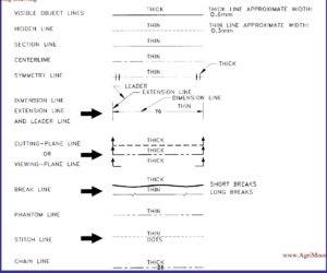
Line Types in Engineering Drawing:
Various types on lines are used for various purposes. The following figure explains the use of different types of lines :
Also Read : https://www.engineinside.com/tool-nomenclature-cnc-turning/


