


What is a dynamo ?
A dynamo is a device which converts the mechanical energy into the electrical energy using the principle of electromagnetic induction.
When a coil (or conductor) is rotated in a magnetic field, the magnetic flux linked with it changes and therefore an e.m.f. is induced in the coil.
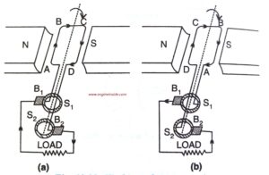
Construction and its main parts : Fig – A shows the construction of an a.c. generator.
The main parts of an a.c. generator are :
(i) the field magnet,
(ii) the armature coil,
(iii) the slip rings, and
(iv) the brushes.
(i) Field magnet : This is a strong horse-shoe permanent magnet NS. An electromagnet run by a d.c. source can also be used as a field magnet.
(ii) Armature coil : This is a soft iron core on which a coil ABCD having a large number of turns of insulated copper wire is wound. This armature coil is rotated rapidly in the magnetic field of the field magnet by the axle fixed to the armature.
(iii) Slip rings : These are the two coaxial metallic rings S1 and S2. They rotate along with the armature coil. The ends of the armature coil are connected to the slip rings S1 and S2.
(iv) Brushes : Two brushes B1 and B2 made of carbon, press lightly against the slip rings S1 and S2 respectively. The external circuit (i.e., load) is connected between the other ends of the brushes. The brushes B1 and B2 do not rotate along with the coil.
Working :
The working of an a.c. generator is shown in Fig. B. Initially let the plane of the coil be perpendicular to the magnetic field (i.e., maximum magnetic field lines pass through the coil). The end A of the coil is connected to the slip ring S1 and the end D to the slip ring S2. The brush B1 touches the slip ring S1 and the brush B2 touches the slip ring S2.
Let by turning the axle, the coil be rotated clockwise. As the armature coil starts rotating, the magnetic flux linked with the coil decreases and therefore an e.m.f. is induced at the ends of the coil due to which an induced current flows in the coil.
When the coil gets rotated by 90° (i.e., the plane of the coil becomes parallel to the magnetic field), the magnetic flux linked with the coil becomes zero and the e.m.f. induced in the coil is maximum. By Fleming’s right hand rule, the direction of induced current in the coil is along ABCD . This is because when the coil rotates clockwise, the arm AB moves outwards (i.e., out of the plane of paper) so the induced current in arm AB is from A to B, while in the arm CD which moves inwards (or into the plane of paper) the induced current is from C to D. Therefore in the external circuit, the current flows from brush B, to brush B, as shown in Fig. B(a).
On further rotation of the coil by 90°, the plane of the coil again becomes normal to the magnetic field and the magnetic flux linked with the coil becomes maximum, so the induced e.m.f. falls to -zero. As the coil further rotates, the magnetic flux linked with the coil decreases and again an induced current flows in the coil in a direction DCBA (i.e., in the external circuit from brush B1 to brush B2) as given by the Fleming’s right hand rule. The e.m.f. again increases to the same maximum value, but in opposite direction. In this position [Fig. B (b)], the arms of the coil AB and CD interchange their position. On further rotation, the e.m.f. reduces to zero when the plane of coil becomes normal to the magnetic field.
Thus in one complete rotation of coil, we get one cycle of alternating e.m.f. in the external circuit. The alternating e.m.f. thus produced has the frequency equal to the frequency of rotation of the coil.
Fig. C represents the e.m.f. induced between the ends of the coil with respect to the position of coil in the magnetic field.
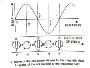
When the plane of the coil is normal to the magnetic field, the magnetic flux linked with the coil is maximum and the e.m.f. induced in the coil is zero. On the other hand, when the plane of the coil becomes parallel to the magnetic field, the magnetic flux linked with the coil becomes zero and the e.m.f. induced in the coil becomes maximum. Thus,
Magnitude of e.m.f.
The magnitude of induced e.m.f. becomes maximum when the magnetic flux linked with the coil reduces to zero from its maximum value. This happens when the plane of the coil comes in the direction of magnetic field from its normal position.
If the coil makes n rotations per second, the
magnitude of induced e.m.f. is given as e=e(max) sin(pi)nt
and the current is expressed as i = i(max) sin 2(pi)nt …
Such a current is called an alternating current. Note that the magnitude of current is continuously changing with time in a periodic manner. In our houses, we have electric supply of frequency 50 Hz (n = 50 Hz i.e., the polarity at the supply terminal change 100 times a second (50 times + and 50 times -).
The e.m.f. induced can be increased by;
(i) increasing the number of turns in the armatur coil,
(ii) increasing the area of armature coil and
(iii) increasing the speed of rotation of armature coil.


 is rotated in a magnetic field, the magnetic flux linked with it changes and therefore an e.m.f. is induced in the coil.)