Mechanism of CNC Machine:
Controller –> Servomotor –> Lead screw rotation –> Table movement –> Position sensed by encoder –> Feedback
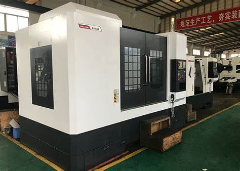
CNC Machine axis movement – Ball Lead screw mech.
CNC Milling spindle rotation – Direct drive
CNC Lathe spindle rotation – Belt Pulley drive
Programming Languages used :
– ISO Mode
— Dialogue mode
Controller :
– Controller is the brain of CNC
– Controller completes the entire important link between computer system and mechanical componenets of CNC
– Primary task to receive signals from computer or indexer and interpret those into mechanical motion through motor output
Feed – Linear advancement of tool against the worpiece in one complete revolution ( Unit – mm/rev )
Rapid feed – Tool moves in XZ plane withou touching workpiece
Cutting feed – feed when tool starts cutting in XZ Plane
CNC Turning Mechanism
X axis movement in turning mechanism:
1. Servo Mech
2. Ball Lead screw mech
Z axis movement
1. Servo Mech.
2. Ball lead srew mech.
Turret Mech.
1. Servo Mech
2. Stepper Mech.
3. Geneva Drive Mech.
4. Gear
CNC Milling Mechanism:
Spindle:
1. Pneumatic Mech.
2. Servo mech
3. Chain and Pulley
4. Bel Drive Mech.
Turret:
1.
2. Cam
3. Gear
4. Pneaumatic Pressure 6 to 8 bars
Types of Taper:
British Taper
BT – 40
Morse Taper
Self Locking


